
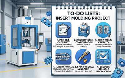
Insert displacement. Mold crush from a misaligned terminal. Brittle overmolded parts from resin sitting too long in an overheated barrel. These are the failure modes that derail insert molding programs—and they almost always trace back to one root cause: the machine was selected on tonnage alone.
Choosing a vertical injection molding machine for insert molding requires a completely different engineering logic than selecting a standard horizontal press. Horizontal machines optimize for throughput and gravity-assisted parts drop. Vertical machines solve a different set of problems: reliably seating inserts against gravity, safely integrating manual or robotic loading, and maintaining precise mold alignment across millions of cycles.
This guide covers the four engineering dimensions that actually determine machine selection for insert molding—and the specification traps that cause most poor purchasing decisions.
Quick Reference: Vertical Injection Molding Machine Selection at a Glance
| Selection Dimension | Key Question | Common Mistake |
|---|---|---|
| Mold capacity | Does the mold base fit the table with full clearance during movement? | Selecting by tonnage without checking tie-bar clearance |
| Table configuration | What is the operator loading tempo and automation roadmap? | Choosing fixed platen for high-volume manual loading |
| Shot size | What is the projected barrel residence time? | Running a small shot on an oversized barrel—resin degrades |
| Screw & nozzle | What resin is being processed? | Using a standard screw with glass-filled engineering resins |
1. Mold Capacity Often Dictates Machine Selection Before Tonnage Does
In horizontal molding, clamping force is nearly the sole metric for machine size class. In vertical insert molding, the physical footprint and structural layout of the mold frequently drive machine selection before tonnage is even calculated.
Insert molding tools are typically built on significantly larger base plates than equivalent horizontal molds, because they must accommodate slide tables or rotary tables for safe insert loading. That extra footprint often pushes the application into a higher machine class.
Clamping Force Baseline Formula
Clamping Force (Tons) = Projected Part Area (in²) × Cavity Pressure (psi) ÷ 2,000 × Safety Factor (1.1–1.2)
Two Selection Traps Unique to Vertical Insert Molding
| Trap | What to Audit | Why It Matters |
|---|---|---|
| Tie-bar clearance for moving molds | Confirm zero interference between mold components and tie bars throughout the full range of slide or rotary table travel—not just in the closed position | A mold that passes the static fit check can still fail the dynamic clearance test |
| Low-pressure mold protection sensitivity | Ask for the machine’s minimum detectable force threshold; confirm the protection zone is programmable by position | A misaligned insert crushed by an insensitive clamp can destroy a multi-cavity tool in a single cycle |
2. Fixed Platen, Slide Table, or Rotary Table: Which Configuration Fits Your Production?
The vertical machine’s fundamental advantage is gravity holding inserts in the bottom mold half during clamp close. The table configuration determines how inserts are loaded and how finished parts are removed—and choosing the wrong one costs either throughput or operator safety.
Configuration Comparison Table
| Configuration | Best Fit | Throughput Impact | Automation Compatibility |
|---|---|---|---|
| Fixed platen | Robotic loading; simple single-insert applications | Lowest—machine idles during manual loading | High with robot arm integration |
| Single slide table | Wire harnesses; oversized PCBs; complex multi-component inserts | Medium—operator works outside clamping zone | Medium |
| Double slide table | High-volume manual loading operations | High—loading occurs in parallel with injection | Medium-high |
| Rotary table injection molding machine | 24/7 mass production; fully automated lines | Highest—all stations run simultaneously | Highest |
Fixed Platen
The mold remains stationary. Injection and part handling occur at the same position.
- Best fit: Semi-automated setups, robotic loading arms, or simple single-insert applications such as a single threaded nut
- Limitation: The operator must reach into the molding area between cycles. The machine idles during loading, which reduces throughput and increases risk in high-volume production
Single / Double Slide Table
The bottom mold half translates out of the clamping zone (single), or two bottom halves alternate in and out (double).
- Best fit: Long wire harnesses, oversized PCBs, or assemblies with multiple components requiring careful sequential placement
- Efficiency advantage: A double slide table allows the operator to load inserts on the outboard station while the machine injects on the inboard station—loading time is removed from the cycle equation entirely, reducing effective cycle time by 30–50% versus a fixed platen at the same operator loading tempo
Rotary Table Injection Molding Machine
The bottom mold rotates—typically 180° or 360°—in 2-station, 3-station, or multi-station layouts.
- Best fit: 24/7 high-frequency mass production and fully automated assembly lines
- Typical 3-station layout:
| Station | Operation |
|---|---|
| Station A | Robotic insert loading |
| Station B | Injection molding |
| Station C | Robotic part removal + vision inspection |
All three stations operate simultaneously, making the rotary table injection molding machine the highest-throughput configuration available for insert molding.
Critical specification: Rotary positioning accuracy and repeatability under load. Mold alignment concentricity across every index cycle directly determines part quality in precision electronics applications. Always request the positioning repeatability specification under production load conditions—not just the unloaded mechanical indexing spec.
3. Shot Size Matching: How to Avoid the Barrel Residence Time Trap
Insert molding regularly presents a specific paradox: a physically large mold paired with a very small injection volume. A common example is a large stamped metal carrier plate requiring only a thin perimeter bead of overmolded plastic. Housing that mold forces a step up to a larger machine frame—but larger frames come with proportionally larger screws and barrels.
The Residence Time Problem
| Scenario | Detail |
|---|---|
| Part shot weight | 10 g |
| Machine barrel capacity | 200 g |
| Barrel utilization per cycle | 5% |
| Cycles before full barrel turnover | ~20 cycles |
| Risk | Resin degrades before injection |
Residence Time Formula
Residence Time (min) = Barrel Capacity (g) ÷ Shot Weight per Cycle (g) × Cycle Time (min)
Thermal Degradation Thresholds by Resin
| Resin | Maximum Safe Residence Time | Visible Degradation Signs |
|---|---|---|
| PA66 + GF (glass-filled nylon) | 5–8 minutes | Splay, yellowing, brittle parts |
| PBT | 5–7 minutes | Discoloration, reduced impact strength |
| PPS | 6–8 minutes | Surface streaks, mechanical property loss |
If the calculated residence time exceeds these thresholds, the standard “20%–80% of barrel capacity” shot sizing rule is insufficient. The correct solution is to specify a reduced-diameter screw or a smaller barrel assembly matched to the machine frame—preserving platen footprint while compressing residence time back into the safe zone. Confirm this option is available before purchase, as not all manufacturers offer it as a standard configuration.
4. Screw and Nozzle Architecture for Engineering Resins
Insert molding rarely runs commodity polymers. The engineering resins it requires impose specific demands on screw and nozzle design that should be treated as mandatory baseline specifications—not optional upgrades.
Screw and Nozzle Specification by Application
| Requirement | Specification | When to Apply |
|---|---|---|
| Wear resistance | Bimetallic screw and barrel (hardened inner bore + corrosion-resistant alloy flight surface) | Any glass-filled resin (GF20, GF30, GF50) |
| Anti-drool / shut-off | Spring-loaded needle shut-off nozzle | All low-viscosity resins: nylon (PA6, PA66), POM |
| Standard open nozzle | Acceptable | High-viscosity resins only: PC, ABS, PS |
Why bimetallic is mandatory for glass-filled resins: A resin with 30–50% glass fiber reinforcement will wear a standard screw within months of production startup. Erratic screw wear causes inconsistent injection pressure and shot volume, degrading part quality and accelerating mold wear in parallel.
Why shut-off nozzles are non-negotiable for nylon: Nylons become extremely low-viscosity when molten. In a vertical press, an open nozzle drools downward between shots, depositing cold slugs on the lower mold surface and contaminating inserts. A spring-loaded needle shut-off nozzle eliminates this failure mode entirely.
5. Pre-RFQ Checklist: Four Data Points to Have Ready
Issuing an RFQ without these four items confirmed produces proposals that cannot be meaningfully compared—and quickly reveals which suppliers are quoting catalog machines versus engineering solutions.
| Data Point | What to Specify | Why It Filters Suppliers |
|---|---|---|
| Insert material and geometry | Rigid metal stamping vs. pressure-sensitive wire harness | Determines whether magnetic lower-mold positioning or ultra-low-pressure clamp protection is required |
| Mold base footprint on table | Exact outer dimensions as mounted to slide or rotary table | Confirms dynamic clearance through full range of motion—not just static fit |
| Actual shot weight per cycle | Net resin weight including runners and cold slug | Enables residence time calculation before barrel size is specified |
| Automation interface roadmap | 3–5 year plan for robots, feeders, vision systems | Determines whether Euromap 67 or Euromap 78 interface must be pre-wired at purchase |
On the automation interface: Retrofitting a Euromap interface after machine delivery is significantly more expensive than specifying it at the point of purchase. If any automation is planned within five years, include it in the initial specification.
Summary: Vertical Injection Molding Machine Selection Framework
| Dimension | What to Audit | Red Flag |
|---|---|---|
| Mold capacity | Tie-bar clearance during table travel; low-pressure protection sensitivity and programmability | Supplier only quotes tonnage without asking for mold base dimensions |
| Table configuration | Operator loading tempo; automation roadmap; target cycle time | Recommending fixed platen for high-volume manual production |
| Shot size | Barrel residence time against resin degradation threshold | No option available for reduced-diameter screw on larger frames |
| Screw / nozzle | Bimetallic spec for glass-filled resins; shut-off nozzle for low-viscosity materials | Standard screw quoted for GF30 or GF50 applications |
In insert molding, there is no universal machine configuration—only the right configuration for your specific insert geometry, resin, production volume, and automation roadmap. The four dimensions above separate a reliable long-term production platform from a machine that generates quality escapes and unplanned downtime within the first year of operation.
Frequently Asked Questions
What is the difference between a vertical and horizontal injection molding machine for insert molding? Vertical machines use gravity to hold inserts in the bottom mold half during clamp close, which significantly reduces insert displacement risk. Horizontal machines require mechanical or magnetic retention of inserts, which adds complexity and cost for most insert molding applications.
What is a rotary table injection molding machine? A rotary table injection molding machine is a vertical press in which the bottom mold rotates—typically 180° or 360°—between multiple stations. This allows insert loading, injection, and part removal to occur simultaneously at different stations, making it the highest-throughput configuration for high-volume insert molding production.
When should I use a slide table versus a rotary table injection molding machine? Use a slide table for applications with long or complex inserts that require substantial loading space, or where production volume does not justify full automation. Use a rotary table injection molding machine for 24/7 mass production, fully automated lines, or applications where maximum throughput is the primary objective.
How do I calculate barrel residence time for insert molding? Residence Time (min) = Barrel Capacity (g) ÷ Shot Weight per Cycle (g) × Cycle Time (min). For PA66+GF, PBT, and PPS, keep residence time below 5–8 minutes to avoid thermal degradation.
Ready to specify the right configuration for your insert molding application? Contact our application engineering team with your mold drawings and insert specifications for a project feasibility review and a custom machine configuration proposal.

